Vehicle Configuration
The ANELLO EVK and Ground INS products require vehicle configurations to be set for proper functionality.
The easiest way to set ANELLO vehicle configurations is using the ANELLO Python Program, which saves all changes to non-volatile flash memory.
Alternatively, the unit can be configured using the APVEH message.
Vehicle Configuration Settings
Vehicle configurations describe the positions of parts in the vehicle setup, which are used in the ANELLO algorithm. All positions are in meters, using the center of the ANELLO unit as the origin and using the coordinate system (X forward, Y right, Z down) in the vehicle frame, i.e. not corrected for mounting orientation of the unit.
Configuration |
APVEH Codes |
Description |
Lever Arm 1 |
g1x, g1y, g1z |
Vector from center of ANELLO unit to antenna 1, in meters |
Lever Arm 2 |
g2x, g2y, g2z |
Vector from center of ANELLO unit to antenna 2, in meters |
Rear Axle Center |
cnx, cny, cnz |
Vector from center of ANELLO unit to center of rear axle, in meters |
Output Center |
ocx, ocy, ocz |
Vector from center of ANELLO unit to desired INS solution position, in meters |
Odometer Position |
wsx, wsy, wsz |
Vector from center of ANELLO unit odometer, in meters |
Antenna Baseline |
bsl |
Baseline length between two antennae, in meters |
Dual Antenna Baseline Calibration
As of FW version 1.2.6, in order to use dual antenna heading, the antenna baseline must be calibrated:
Install the ANELLO unit and antennae on the vehicle.
Navigate to Vehicle Configurations menu, select Edit, then Antenna Baseline.
For most users, we recommend using the Auto calibrate feature. Before you perform auto-calibration, mount the antennae in the desired position on vehicle and ensure the antennae have full open sky view. The calibration takes 2-5 minutes where the ANELLO unit will measure the baseline between the antennae to sub-2cm accuracy and save the resulting configuration automatically.
If you install the ANELLO unit using a CAD model and know your antenna baseline to sub-2cm accuracy, you can use th Enter manually option to manually set this configuration. Similarly, you may also use Calibrate from lever arms if you are certain of your lever arm measurements to sub-cm accuracy.
ZUPT Calibration
As of FW version 1.3.24, algorithm improvements were made to better take advantage of stationary periods. To utilize these improvements, a stationary period must be calibrated using the ANELLO Python program:
Ensure the unit is already installed on the vehicle and the vehicle is turned on and stationary.
In the Python tool, navigate to Vehicle Configurations, select Edit, then ZUPT.
Leave the vehicle on, stationary, and undisturbed for 2 minutes while the calibration is being peformed.
Once complete, the calibrated “ZUPT” values will appear under the Vehicle Configurations
Mounting ANELLO Unit
The ANELLO unit should be mounted securely on a flat surface to avoid movement of the unit during vehicle testing. The mounting location of the ANELLO EVK and Ground INS is flexible and can be configured for various installation positions and orientations. For the least complexity, we recommendation mounting the unit above the center of the vehicle’s rear axle with the X-Axis facing forward along the direction of travel.
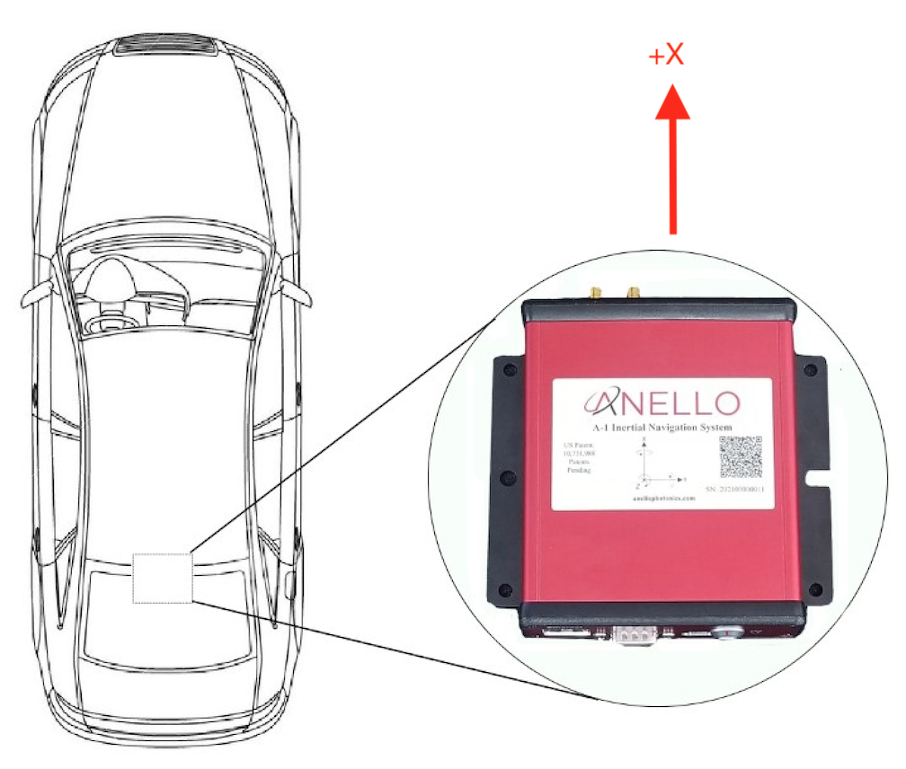
Default Installation Location
If the unit is oriented differently (e.g. backwards or upside down), the “Orientation” configuration must be configured using the ANELLO Python Program. See Unit Configurations for orientation options.
In addition, if the unit is misaligned from the vehicle axis in either roll, pitch, or heading, the “Installation Misalignment Angle” configuration must also be set. If the misalignment angles are unknown, the roll and pitch misalignment can be measured using the these procedures.
Antenna Mounting
The antennae provided with the ANELLO EVK magnetically mount to the vehicle roof. Alternative GNSS antennae can be used, as long as they support dual band and all constellations. Please avoid placing antennae on significantly curved surfaces or below obstructions which would reduce available sky view. For best performance, it is recommended to orient both antennae in the same direction, and ensure there is a ground plane with a diameter of at least 10 cm (4 in). Magnetic mounting to the roof of a car acts as an effective ground plane.
Units received after Nov 1, 2022 and with firmware v1.0 or later will have dual GNSS functionality. Antennae must be separated by at least 0.6 meters and accurate lever arms must be set. Errors in the lever arm settings will directly cause errors in vehicle.
If you are on a firmware version earlier than v1.2.6, ANT1 must be in the back and ANT2 in the front. On firmware v1.2.6 and later, antennae can be positioned in any orientation on the vehicle as long as accurate lever arms are set.
Odometer Input
For extended GNSS-denied testing, it is recommended to send odometer input (including both speed and direction) to the ANELLO EVK or Ground INS. This can be done by sending an APODO message to the configuration port of the ANELLO unit. A few recommended odometer options are:
If you have access to the vehicle CAN bus, you can read in the directional speed from the CAN bus to the computer used to connect to the EVK or Ground INS. Then, construct and send the APODO message to the ANELLO unit.
An external wheel speed sensor can be installed on the vehicle. ANELLO recommends the Pegasem WSS, though it is not robust enough to suit rough terrains.
A radar odometer can be installed on the vehicle. ANELLO recommends the Pegasem GSS.
Supported Vehicle Types
The ANELLO Ground INS and EVK algorithm is currently designed for wheeled land vehicles. Please contact ANELLO about support for other vehicle types.