Mechanicals
ANELLO EVK
The ANELLO EVK features a 4-pin power connector which includes PPS input (PPS1) and output (PPS2) signals. It also features USB C, Ethernet, and CAN connectors, as well as two SMA RF antennae input.
EVK SCD Drawing: PDF

Note
As shown in the image above, the power connector includes two additional pins: PPS Out and Sync In. The power connector included in the EVK kit includes two wires, where the black wire is PPS Out and the green wire is Sync In.
Power Connector info: https://www.lemo.com/en/products/low-voltage-connector/b-connector
Mating Connector: https://www.lemo.com/pdf/FGG.0B.304.CLAD52.pdf
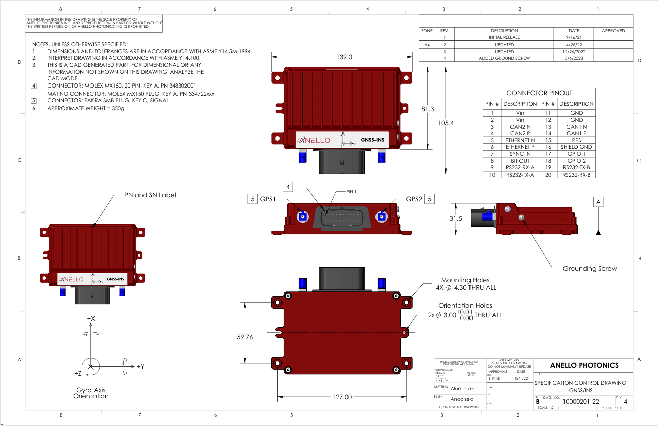
ANELLO Ground INS
The ANELLO Ground INS features a 20 pin Molex MX150 connector and two FAKRA SMB GNSS connectors. The case housing is aluminum with an anodized finish. The ground pins (11, 12) are electrically connected to the case. There is also a case ground screw on the side of the case.
Ground INS SCD Drawing: PDF
Note
If you purchased the Ground INS Evaluation Kit, a schematic of the breakout cable can be downloaded here
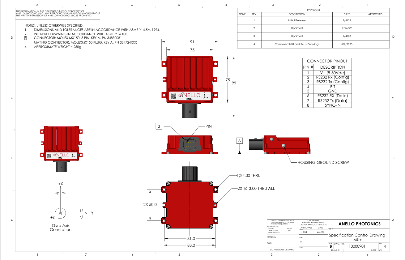
ANELLO Ground IMU
The ANELLO Ground IMU features an 8 pin Molex MX150 connector. The case housing is aluminum with an anodized finish. The ground pin is electrically connected to the case. There is also a case ground screw on the side of the case.
Ground IMU SCD Drawing: PDF
Note
If you purchased the Ground IMU Evaluation Kit, a schematic of the breakout cable can be downloaded here
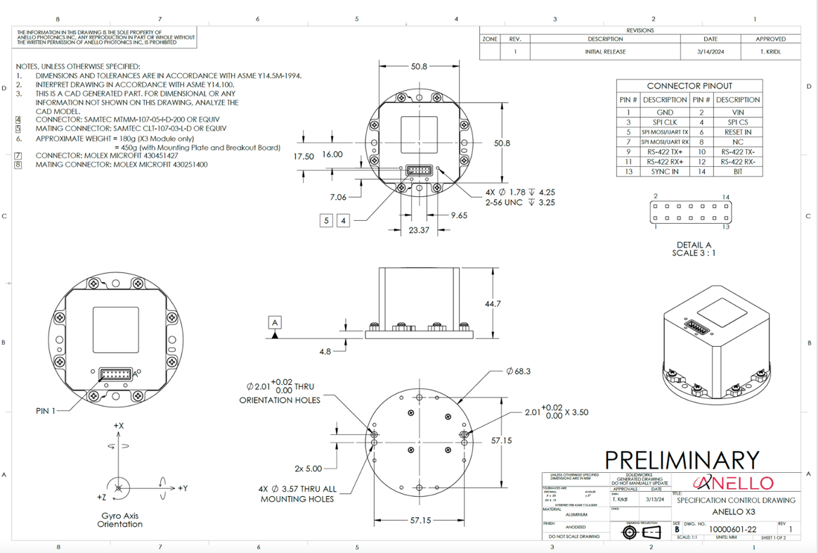
ANELLO X3
The ANELLO X3 features a 14 pin Molex Microfit 430451427 connector. Note that if your X3 serial number is below 830, the unit will need to be mounted on the heat sinking mounting plate shipped with the unit. If removed from the plate, the X3 should NOT be mounted directly onto a thermal insulator such as plastic. It will need to be mounted directly to a thermally conductive surface or mounted such that convective air flow is allowed across all surfaces of the device. This is required to keep the internal temperatures below critical when operating environment is at the extreme of 50 °C.
X3 SCD Drawing: PDF
Note
If you purchased the X3 Evaluation Kit, a schematic of the breakout cable can be downloaded here
Note
Please note that the X3 SCD and breakout cable drawings reflect different use cases. The X3 SCD shows the raw pinout for direct connection to the X3, while the breakout cable includes a breakout board that reassigns certain pins (e.g., replacing unused SPI lines with additional grounds) for ease of use in an evaluation setting. This results in differing pin labels, but the overall functionality remains consistent.